MY GROUND HUM BRAIN TEASER

  • Thread starter john eagle
  • Start date
  • This site may earn a commission from merchant affiliate links like Ebay, Amazon, and others.

john eagle

Member
Joined
Nov 2, 2015
Messages
38
Reaction score
36
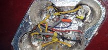
As mentioned in another thread I have a a ground hum that's above my pay grade. This started as a result of gutting the wiring of a standard LP 2 x vol./2 x tone configuration. This is only my 3rd experience building a wiring harness and my 1st time building a LP harness. As a result I am rather green when it comes to troubleshooting. Before I break down the results of the continuity tests I will share that I resoldered the grounds of the switch and jack but to no avail. Without further ado here are the results of the continuity tests.
BRIDGE TO :
POTS - ✅
GROUND SOLDERS ON POTS :✅
JACK :❌
SWITCH :❌
BRIDGE PU. :✅
NECK PU.:❌
SHIELDING :✅

SWITCH TO :
POTS:❌
JACK:✅

POTS TO POTS :✅

So as you can see it's rather a mess and I'm not sure where to begin. My common sense mechanism seems to have failed me. Why, for instance, would it be cold solders on the pot grounds when the multimeter alerts there is continuity? And why do I have continuity between the jack and the switch but not the bridge? Then there's the neck pickup!
I'm this close to taking it to a guitar tech. Talk me off the ledge !
 

soulman969

Moderator
Staff Member
Joined
Dec 7, 2015
Messages
5,506
Reaction score
8,185
Location
Fort Collins, CO
I don't know ow to do that. Don't I need to upload the pics to some cloud first?
No, you can upload them directly but what I find easiest myself is to save the image to my lap top so I can resize it if necessary. Then our system will allow you to simply upload it from there.

Here's an example of one of mine I've uploaded. Use the icon in the task bar above that says "Insert Image". You can either drop the image or hit "click here", go to the computer file where you store your photos, then select those you want to upload. If you get a prompt saying the image it to large you can reduce the size. There's an entire thread on methods for doing it.

es339.jpg
 

imnotcreative

Well-Known Member
Joined
Dec 30, 2020
Messages
524
Reaction score
917
Location
Zaandam, The Netherlands
Anything up to 1MB should work. close-up photo's would be optimal to be able to inspect the wiring.

When it comes to cold solder joints, your multimeter most likely sends out a higher voltage to test continuity than what the pickups will generate. There might be some resistance without knowing. Myself working on wiring in a guitar i never use the continuity tester on the multimeter. I always check the resistance. When a connection is good it should read 0 or close to it. If there is an occasional interuption in the signal path (bad connection etc) it could very well read properly of you using the multimeter prongs to make a proper connection unknowingly.

My first question would be, do you have sound coming from both pickups? If so we atleast know there is a ground connected on either pickup. No connection to either the hot or the ground side will be a break in the circuit and it will not produce a signal.

Second, how does your ground wire run? Connecting all 4 pots together and then from both volume pots to the switch? That could cause a groundloop. Or act a bit as an antennae picking up noise. This should be audible on the neck pickup aswell

If the 4 pots are connected together and from there go to the ground of the output jack and there is a bad connection on the ground to the switch that wire going to the switch and the switch itself may act as an antennae introducing hum. There would still be an output signal as the ground for the pickups go straight from the pots to the jack as long as there is a good signal going through the switch.

Could be many things. If you shielded the cavities well you wouldn't even need to wire the grounds of the pots together. The conductive shielding should connect all the metal housings of the pots together, just have to make sure there is a ground wire to the switch because its in a different location. In theory you if you do a proper shielding job in an SG you wouldn't even need a ground wire. only the grounds ot the pickups to the pots. The shielding should connect the housings of the pots, switch and output jack all together as one circuit. Just need to connect the signal wires and the capacitors and the pickups.

Photo's would be a big help. There are many ways one could do the wiring so there is no real saying what it is without knowing the circuitry.
 

imnotcreative

Well-Known Member
Joined
Dec 30, 2020
Messages
524
Reaction score
917
Location
Zaandam, The Netherlands
Test photo

Hmm, by the looks of it you grounded all pots together and from there on probably a wire going from the bridge volume pot towards the switch? It's a bit hard to see.. If that is the case, do you have any hum on your neck pickup? if not, if you run the ground from the bridge volume pot towards the switch and then the output jack there shouldn't be a problem there.

In that case i would search between the bridge pickup, the bridge volume and tone pots. Don't mess with the ground wire going to the switch if it is connected as above and the neck pickup has no problems.
You could try and desolder the capacitor from the tone pot. If the humming stops it has something to do with the tone pot. If not, it's somewhere in the connection between the pickup and the pot or the pot leg to ground.

Your shielding looks a little wrinkly, have you made sure there is absolutely no way a connection can be made between the crimps of the potentiometer legs and the shielding? I could be wrong but your pots seem to be fairly close to the shielding. You could try an extra washer if you have one, or just put some tape over the crimps of the legs to act as a barrier and prevent an unwanted connection


Latest posts

Top